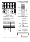
DIAGNOSTIC DISPLAY PANEL CODES
The following table is a brief description of diagnostic,
operational and error codes that may be displayed.
Error codes can be designated for specific customer
requirements and may not be listed here. Refer to the
technical documentation that accompanies your
system for specific customer defined error code
designations.
(VC — Voltage control version only)
(PWM — Pulse width modulation version only)
Operational Codes
x x 0
Receiving correct signal, no E-Stop, system
started
x x 1
Receiving correct signal, BMS-2 in E-Stop, no
E-Stop from TX
x x 2
Receiving correct signal, BMS-2 in E-Stop,
E-Stop transmission from TX
x x 3
RF interference
0 0 4
Not receiving signal, no RF communication, or
TX is turned off
0 0 0 .
Flashing dot after third digit, change the status
with each correct received telegram (green
LED)
0 0 . 0
Flashing dot after second digit indicates
programming mode (Quick-Set)
1 x x
Output 1 (up to  activated, joystick not in
neutral position. System will not start if joystick
is not in neutral position.
Error Codes
E x x
Error Codes are assigned numbers based on
customer requirements.The errors listed below
may or may not be applicable to your system.
See Technical Documentation for specific
codes.
E 0 0
Joystick 1 error — joystick 1 out of neutral
without closed safety switch
E 0 1
Joystick 2 error — joystick 2 out of neutral
without closed safety switch
E 0 2
Joystick 3 error — joystick 3 out of neutral
without closed safety switch
E 0 3
Joystick 4 error — joystick 4 out of neutral
without closed safety switch
E 0 4
Joystick 5 error — joystick 5 out of neutral
without closed safety switch
E 0 5
Joystick 6 error — joystick 6 out of neutral
without closed safety switch
E 0 6
Joystick 7 error — joystick 7 out of neutral
without closed safety switch
E 0 7
Joystick 8 error — joystick 8 out of neutral
without closed safety switch
E 0 8
Over-current 0 error, over-current on E-Stop
circuit
E 0 9
Over-current 1 error, over-current on switching
output 1-6
E 1 0
Over-current 2 error, over-current on switching
output 7-12
E 1 1
Over-voltage error >35V
E 1 2
Under-voltage error <8V
E 1 3
DV1 (Y0) read back error
E 1 4
SW output 1 read back error
E 1 5
Valve Supply 1 read back error (VC)
E 1 6
Valve Supply 2 read back error (VC)
E 1 7
Valve Supply 3 read back error (VC)
E 1 8
Valve Supply 4 read back error (VC)
E 1 9
Valve Supply 5 read back error (VC)
E 2 0
Valve Supply 6 read back error (VC)
E 2 1
Valve Supply 7 read back error (VC)
E 2 2
Valve Supply 8 read back error (VC)
E 2 3
AK1 analog output read-back error (VC)
E 2 4
AK2 analog output read-back error (VC)
E 2 5
AK3 analog output read-back error (VC)
E 2 6
AK4 analog output read-back error (VC)
E 2 7
AK5 analog output read-back error (VC)
E 2 8
AK6 analog output read-back error (VC)
E 2 9
AK7 analog output read-back error (VC)
E 3 0
AK8 analog output read-back error (VC)
E 3 1
PWM output shortcut detection (PWM)
E 3 2
Valve 1 error input (VC)
E 3 3
Valve 2 error input (VC)
E 3 4
Valve 3 error input (VC)
E 3 5
Valve 4 error input (VC)
E 3 6
Valve 5 error input (VC)
E 3 7
Valve 6 error input (VC)
E 3 8
Valve 7 error input (VC)
E 3 9
Valve 8 error input (VC)
E 4 0
CAN bus data timeout error (Hetronic and
HMF)
E 4 1
Start locking input error
E 4 2
RF-DK start locking error, start locked DK is not
in neutral position during system start
Error codes of 50 or greater are start-up or online test
errors and require device re-start to clear.
E 5 0
CPU_TEST_FAILED
E 5 1
WATCHDOG_TEST_FAILED
E 5 2
INTERRUPT_TEST_FAILED
E 5 3
TIMER_TEST_FAILED
E 5 4
EXTRAM_TEST_FAILED
E 5 5
INTRAM_TEST_FAILED
E 5 6
INTPRAM_TEST_FAILED
E 5 7
PFLASH_TEST_FAILED
E 5 8
STACK_OVERFLOW_DETECTED
E 5 9
MAIN_LOOP_TIME_FAILED
E 6 0
OP_COUNTER_ERROR
E 6 1
Serial EEPROM checksum error
E 6 2
Internal HW error — E-stop pulses timeout
16
Specifications:1618/1618100-rx_bms2pwm.pdf file (14 Feb 2023) |
Accompanying Data:
HETRONIC RX BMS2-PWM Receiver PDF Operator’s Manual (Updated: Tuesday 14th of February 2023 06:03:12 PM)
Rating: 4.4 (rated by 55 users)
Compatible devices: HT-R570, SKYSTAR 2, UFS 710si, airFiber AF 60, Axroll, R-V905, ATS1745, RX 14-HL.
Recommended Documentation:
Text Version of HETRONIC RX BMS2-PWM Operator’s Manual
(Ocr-Read Summary of Contents, UPD: 14 February 2023)
-
16, HETRONIC RX BMS2-PWM 16 DIAGNOSTIC DISPLAY PANEL CODES The following table is a brief description of diagnostic, operational and error codes that may be displayed. Error codes can be designated for specific customer requirements and may not be listed here. Refer to the technical documentation that accompanies…
-
2, HETRONIC RX BMS2-PWM 2 Introduction . . . . . . . . . . . . . . . . . . . . . . . . . . . . . 3 The Manual . . . . . . . . . . . . . . . . . . . . . . . . . . . 3 Production and System Numbers . . . . . . . . . . 3 Unauthorized Replacement Parts . . . . . . . . . . 3 Before Attempting to Operate This Syste…
-
4, 4 10. Always have batteries in the battery charger to ensure the availability of fully charged batteries. 11. Installation, setup and service must be performed by authorized personnel only. 12. Use only Hetronic spare parts. HETRONIC SYSTEM COMPONENTS The Hetronic radio remote control sys…
-
3, 3 INTRODUCTION Thank you for purchasing the Hetronic radio remote control system. Hetronic radio remote controls are the highest caliber in remote control value, performance and safety. Hetronic radio remote controls use the latest frequency synthesizer technology to eliminate the problem…
-
12, 12 7. Wait approximately 3 seconds until the second buzzing sound has finished. 8. Twist the key one quarter turn further to the program position. (This is only possible with the red programming key.) Press the «Start/horn» button for at least one second. 9. To set minimum speed — Deflect the requested …
-
19, 19 DEFINITIONS Acoustic signal A buzzer or other sound intended to be heard as an alert. Analog signal Proportional — stepless or infinite control Belly box A transmitter that is secured to the front of the operator’s body by a belt, strap or breastplate/harness. Coder Converts parallel signals into a serial da…
-
21, 21 WARRANTY WRTY_002 Warranty & Terms April 2003 Hetronic USA Limited Warranty and Terms of Sale www.hetronic.com Price: Subject to Change Without Notice Terms: Net 30 Days F.O.B: Hetronic USA, Inc. Oklahoma City, Oklahoma Hetronic, Inc., hereafter referred t…
-
13, 13 IMPORTANT: If the ADMO settings of the transmitter and receiver do not match, the system will not function. CAUTION: AVOID INJURY OR DAMAGE — Operating the transmitter without its antenna could destroy the final stage of the RF module. DO NOT attempt to change the Hetronic pre-set frequenc…
-
14, HETRONIC RX BMS2-PWM 14 If the system does not operate after normal start-up as described in Operation Section of this manual, follow the recommended troubleshooting sequence to help isolate the cause and determine corrective action. The BMS-2 Receiver displays Operational Status and Error Codes …
-
HETRONIC RX BMS2-PWM User Manual
-
HETRONIC RX BMS2-PWM User Guide
-
HETRONIC RX BMS2-PWM PDF Manual
-
HETRONIC RX BMS2-PWM Owner’s Manuals
Recommended Instructions: S660C, 911.92391, Mixels Footi 41521


-
Denon AVC-A1XV
The Operating Manual for DENON AV Receiver/Amplifier firmware update. Page 1 / 18 D&M Holdings, INC. The Operating Manual for DENON AV Receiver/Amplifier firmware update. “DENON Flash Rom Writer Compact Version.” Model Name: AVR5805/AVC-A1XV Version: AVCA1XV: FWCV_AVCA1XV_V0003 AVR5805: FWCV_AVR5805_V0003 Date: 2005-8-5 DENON D&M Holdin …
AVC-A1XV 18
-
Audiovox GMRS2000
General Mobile Radio ServiceGMRS-2000! CTCSS Sub Tone! (38 Frequency)! VOX Operating! Scanning! Monitor! Weather Radio Band (10Channels)! Weather Alert! Key Pad Lock! Back Light LCD Display! Battery StatusIndicator! Emergency Channel! Choice of Battery- RechargeableBattery- Standard AlkalineTRIDENT TECHNOLOGY INTERNATIONALFCC ID: PDHGMRS-2000EXHIBIT #: 6 …
GMRS2000 15
-
Sony STR-DA2ES — Fm Stereo/fm-am Receiver
SERVICE MANUALFM STEREO FM-AM RECEIVERSPECIFICATIONSSTR-DA2ES/DB1080Photo: STR-DA2ESVer 1.1 2003.079-874-061-02 Sony Corporation2003G05-1 Home Audio CompanyC 2003.07 Published by Sony Engineering CorporationUS ModelCanadian ModelSTR-DA2ESAEP ModelUK ModelE ModelSTR-DB1080– Continued on next page –This receiver incorporates Dolby* Digital and Pro Logic Surroundand the DTS** Digital Su …
STR-DA2ES — Fm Stereo/fm-am Receiver 110
-
Gigawave D-Cam Clip-On
D-Cam Clip-On Operators Manual Issue 1 Page 1 of 1 UNUM-CCAM -0104 The information contained in this manual remains the property of Gigawave and may not be used, disclosed or reproduced in any other form whatsoever without the prior written permission of Gigawave. D-Cam Clip-On OPERATORS MANUAL Copyright 2005 Gigawave Limited …
D-Cam Clip-On 30
Operating Impressions, Questions and Answers:
ESC is possibly soft-bricked; try to flash ESC with ST-Link (ESx, Max)
Table of Contents for HETRONIC RX BMS2-PWM:
-
5 When the transmitter is turned on, it performs a self-test to be sure that the circuitry is within designated parameters. If an error is detected, the transmitter will not transmit any motion signals. The BMS-2 receiver display will show «0 0 4» indicating a passive E-Stop condition in the transmitter. Receiver Safe Mode The following conditions cause the receiver to go into its Safe mode: • Radio signal interference • Transmitter out of operating range • E-Stop button is a
-
14 If the system does not operate after normal start-up as described in Operation Section of this manual, follow the recommended troubleshooting sequence to help isolate the cause and determine corrective action. The BMS-2 Receiver displays Operational Status and Error Codes to help diagnose problems that may occur with the system. The Operational Status codes are shown in the Operation Section of this manual. Error Codes a
-
YOUR #1 PARTNER IN RADIO REMOTE CONTROLS Operator Manual Hetronic USA 4300 Highline Blvd., Bldg. A Oklahoma City, OK 73108 405-946-3574 Fax 405-946-3564 OPMN_BMS2_0001.0 12/04 www.hetronic.com Hetronic Canada 45 Sinclair Avenue Halton Hills, Ontario L7G 4X4 +1-800-816-4459 Fax +1-905-702-0501 © 2004 Hetronic, Inc. All rights reserved. No part of this publication may be reproduced, transmitted, transcribed, stored in a retrieval system, or translated into a
-
10 SYSTEM FEATURES Receiver Display The receiver has a 3-digit, 7-segment display on the outside of the housing to show operation status and Error Codes. The following table shows basic operational status codes. Error Codes are assigned per specific customer requirements. Speed Reduction/Speed Select Function This radio remote control system is equipped with a speed control function. It allows speed reduction to 75%, 50%, and 25% of the maximum speed using a switch on the transmitter. Other speed select options can be p
-
9 IMPORTANT: To avoid accidental start-up, always engage the E-stop pushbutton and switch the transmitter «OFF» when not in use. When the transmitter is not attached to the operator, the key switch should be removed and stored in a secure place. EMERGENCY STOP For all emergency situations, push the E-Stop pushbutton in. To restart the system
-
19 DEFINITIONS Acoustic signal A buzzer or other sound intended to be heard as an alert. Analog signal Proportional — stepless or infinite control Belly box A transmitter that is secured to the front of the operator’s body by a belt, strap or breastplate/harness. Coder Converts parallel signals into a serial data message Decoder Coverts a serial data message into parallel signals Digital signal On/off control Latching control The function activates when the control is pushed
-
8 HOLDING THE TRANSMITTER Hold the transmitter with the control panel facing you. Be sure that you are able to easily read any text and understand operation symbols. If your transmitter contains a Tilt Sensor Switch, be sure it is not activated or the transmitter will not start. If a belt or strap is provided with your transmitter, use it at all times. The belt or strap is designed to reduce stress and increase safety. The safety checks described in the following
-
13 IMPORTANT: If the ADMO settings of the transmitter and receiver do not match, the system will not function. CAUTION: AVOID INJURY OR DAMAGE — Operating the transmitter without its antenna could destroy the final stage of the RF module. DO NOT attempt to change the Hetronic pre-set frequency or the 16-bit address. Personal injury and property damage could result from transmission interference and may void the warranty.
-
7 Be sure that the Diagnostic Display panel is clearly visible. The receiver wiring is critical for proper system operation. Make all connections with good quality contacts or solder joints to ensure proper electrical contact. Supply voltage and ground wiring are crucial and must be connected to reliable connecting circuitry. Do not use a chassis ground for this equipment. The ground wire must be connected directly to
-
2 Introduction . . . . . . . . . . . . . . . . . . . . . . . . . . . . . 3 The Manual . . . . . . . . . . . . . . . . . . . . . . . . . . . 3 Production and System Numbers . . . . . . . . . . 3 Unauthorized Replacement Parts . . . . . . . . . . 3 Before Attempting to Operate This System . . . 3 System Components . . . . . . . . . . . . . . . . . . . . 4 RX BMS2-PWM Standard Features . . . . . 4 RX BMS2-VC Standard Features . . . . . . . 4 Theory of Operation. . . . . . . . . . . . . . . . . . . . . 4 Sa
-
20 ABBREVIATIONS A/D Analog to digital conversion AK Analog channel (German: Analog Kanal) AMP Ampere AWG American Wire Gauge BPS Bits per second CPU Central Processing Unit DK Digital channel (German: Digital Kanal) EMC Electromagnetic compatibility EMI Electromagnetic immunity EPROM Electrical programmable read-only memory FM Frequency modulation GND Ground HF High frequency KHz Kilohertz LED Light emitting diode LTO Lift to operate mAH Milliampere hours mA Millampere msec Millisecond MHz Megahertz MOV Metal Ox
-
4 10. Always have batteries in the battery charger to ensure the availability of fully charged batteries. 11. Installation, setup and service must be performed by authorized personnel only. 12. Use only Hetronic spare parts. HETRONIC SYSTEM COMPONENTS The Hetronic radio remote control system consists of a receiver and transmitter with belt, battery charger, and two rechargeable batteries. RX BMS2-PWM Receiver Standard Features • 1 E-Stop output • 1 safety valve output • 11 hardwired digital outputs • Expansion of up to 16 a
-
21 WARRANTY WRTY_002 Warranty & Terms April 2003 Hetronic USA Limited Warranty and Terms of Sale www.hetronic.com Price: Subject to Change Without Notice Terms: Net 30 Days F.O.B: Hetronic USA, Inc. Oklahoma City, Oklahoma Hetronic, Inc., hereafter referred to as Company, guarantees all items manufactured by it against any defects of material and/or workmanship for a period of one year from the date of shipment. Company makes NO OTHER WARRANTY, EXPRESSED
-
3 INTRODUCTION Thank you for purchasing the Hetronic radio remote control system. Hetronic radio remote controls are the highest caliber in remote control value, performance and safety. Hetronic radio remote controls use the latest frequency synthesizer technology to eliminate the problems typically associated with radio remote control systems. THE MANUAL Before operation of unit, carefully and completely read your manuals. The contents will provide you with an understanding of safety instructions and controls d
Questions, Opinions and Exploitation Impressions:
You can ask a question, express your opinion or share our experience of HETRONIC RX BMS2-PWM device using right now.

52
28000 Owner’s Manual
BMS-2 Receiver Troubleshooting
Available on some systems. Consult BMS-2 Operator Manual for details.
Problem
Probable Cause
Correction
System will not initialize after
normal start-up procedure.
E-Stop reset
Joystick or paddle lever not in
center position.
E-Stop switch engaged.
Battery fully discharged.
No power to the receiver.
Push the Start button again. If the system is being initialized from an E-Stop
condition, the Start button must be pressed twice — first to clear the E-Stop, then
again, to start the system.
Be sure that all joysticks and paddle levers are in center position when the Start
button is activated.
Pull out E-Stop switch. Restart system by pressing Start twice.
Check battery to ensure a full charge. Replace with fully charged battery if
necessary.
Check the diagnostic Display on the side of the receiver to be sure power is
applied. Ensure that the system is securely grounded to the negative battery
terminal. The Display also indicates normal transmitter communication,
interference, and E-Stop conditions.
The transmitter is turned on,
but does not transmit (Power
LED not flashing)
Battery is discharged.
Coder board fuse.
Broken key switch.
Coder board failure.
Replace battery with a fully charged battery.
Check fuse and replace if necessary.
Check wiring on key switch. Replace key switch, wiring or contact element.
Contact Hetronic or your Dealer.
Transmitter is transmitting
(Power LED flashing), but
crane will not respond.
E-Stop switch engaged.
Transmitter out of range.
Joystick, paddle lever or switch
not in center position when
transmitter turned on.
Receiver power off.
Blown fuse in receiver.
E-Stop failure in transmitter.
E-Stop failure in receiver. Red E-
Stop LED on decoder board is
illuminated.
E-Stop module failure.
Pull out the E-Stop pushbutton and press the Start/Horn pushbutton.
Take the transmitter back into the range of the receiver. Press the Start/Horn
pushbutton.
Ensure that all control devices are in center (neutral) position when the Start button
is activated.
Turn on power to receiver.
Check all fuses. Replace if necessary.
Check E-Stop pushbutton for damage. Check wiring to contact element for broken
or disconnected wires. Repair or replace E-stop pushbutton or wiring.
Check wiring on E-Stop module, decoder module, E-Stop decoder module. Secure
any loose connections.
Replace E-Stop module.
All crane/machine
motions operate
intermittently
Receiver antenna loose or
missing.
External antenna (if used) has
loose connection, poor grounding
or interference.
Connector wiring too close to
power wiring.
Connector inside receiver is
loose.
Tighten or replace antenna.
Tighten antenna and ground connection. See «Connecting an External Antenna»
Section for operational precautions.
Control wiring must be run separately from power wiring.
Check all connectors, reseat if necessary.
Some crane/machine
motions operate
intermittently
Crane/machine motion wiring may
be loose.
Connector inside receiver is
loose.
Connector wiring too close to
power wiring.
Check wiring from receiver to plug and from plug to crane/machine motion
actuator.
Check all connectors, reseat if necessary.
Control wiring must be run separately from power wiring.